
Progressive loss of the working profile, local chipping, fracture and mounting-eye damage need different evidence. If a hammer is removed earlier than expected, record the damage location, verified work performed, removal reason and condition of the other hammers from the same operating period.
Use those records with feed, mounting and operating changes to decide whether to investigate material, geometry, retained components or operating duty. Greater hardness may help one failure mode while leaving another unresolved.
Locate the damage before comparing materials
This guide concerns hammers in a hammer crusher, with a free-swinging hammer used as the structural example. An HSI blow bar is a different component. For that part, use the HSI blow bar material guide.
In a free-swinging arrangement, a hammer pivots on an off-centre pin or bolt carried by the rotor. HAZEMAG's HDS description provides one documented example of hammers mounted between rotor discs. The central rotor shaft and the hammer pin have different functions; the main-shaft and hammer-pin guide explains that distinction.
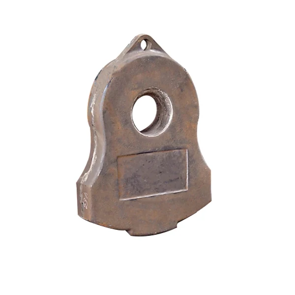
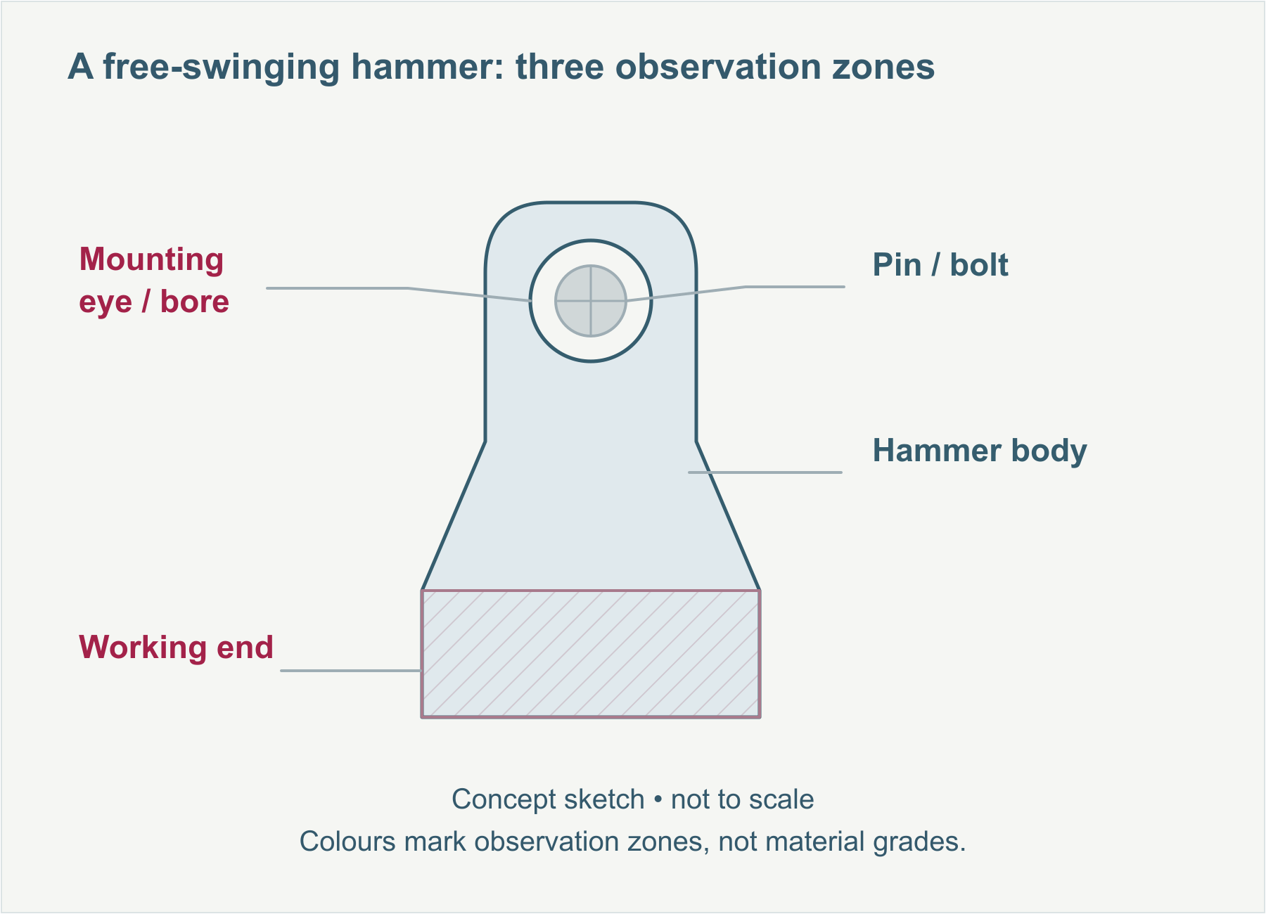
Record the working end, body and mounting eye separately. Include an overall photograph as well as close-ups. A photograph of a chipped edge alone does not show whether the mounting region, pin or adjacent hammer is also damaged.
Collect these observations during maintenance under the machine's applicable isolation, access and handling procedures. The sketch does not define how to remove or turn a hammer.
What can cause premature crusher hammer wear or breakage?
Abrasive feed can consume a hammer's working profile, while impact events, material condition, geometry and support can contribute to chipping or fracture. These mechanisms can coexist. A study of high-chromium hammers crushing barite identified interacting impact and abrasive wear using material and surface examination. It is a case-specific finding, not a diagnosis for a different feed or hammer construction.
A worn working surface shows where material has been consumed. A missing corner or crack introduces a different question: did the part progressively lose its profile, or was there a distinct damage event? Keep the timing and location of each observation.
Why a hard hammer can still lose material quickly
In the barite study, the examination found grooves and cutting together with cracked or detached carbides. The useful distinction is between resisting surface cutting and retaining the structure that carries the load. A hard constituent can resist abrasion yet contribute little once it fractures or loses support. A bulk hardness reading does not describe that whole sequence.
This is why “too soft” and “too brittle” are hypotheses to test, rather than diagnoses from the amount of missing metal. Feed characteristics, construction, heat treatment and loading must be considered with the damage evidence. Grooves in a photograph help locate an examination; they do not identify microstructure or establish the origin of a crack.
Swipe or scroll to see all columns.
| Observation | Competing explanations to separate | Evidence that changes the next decision |
|---|---|---|
| Working end becomes thinner or rounded | A higher wear rate versus more work performed before inspection | Starting/later profiles and verified tonnes over the same interval; service days cannot separate the two |
| One rotor position loses more profile | A position-related exposure versus a problem following one identified hammer | Part and position history across permitted moves; compare whether the pattern stays at the location or follows the part |
| A corner chips or a section breaks | A recorded overload event versus inadequate resistance to the actual duty, or another local defect | Event chronology, the fracture location, retained pieces and technical examination; the final fracture alone does not establish the initiating event |
| The eye or surrounding body is damaged | Changed contact/loading at the interface versus a geometry or material issue in the hammer | Drawing-based geometry, condition of the pin and support, contact evidence and material examination considered together |
These are investigation routes. A visible pattern can direct the next check without establishing a single cause.
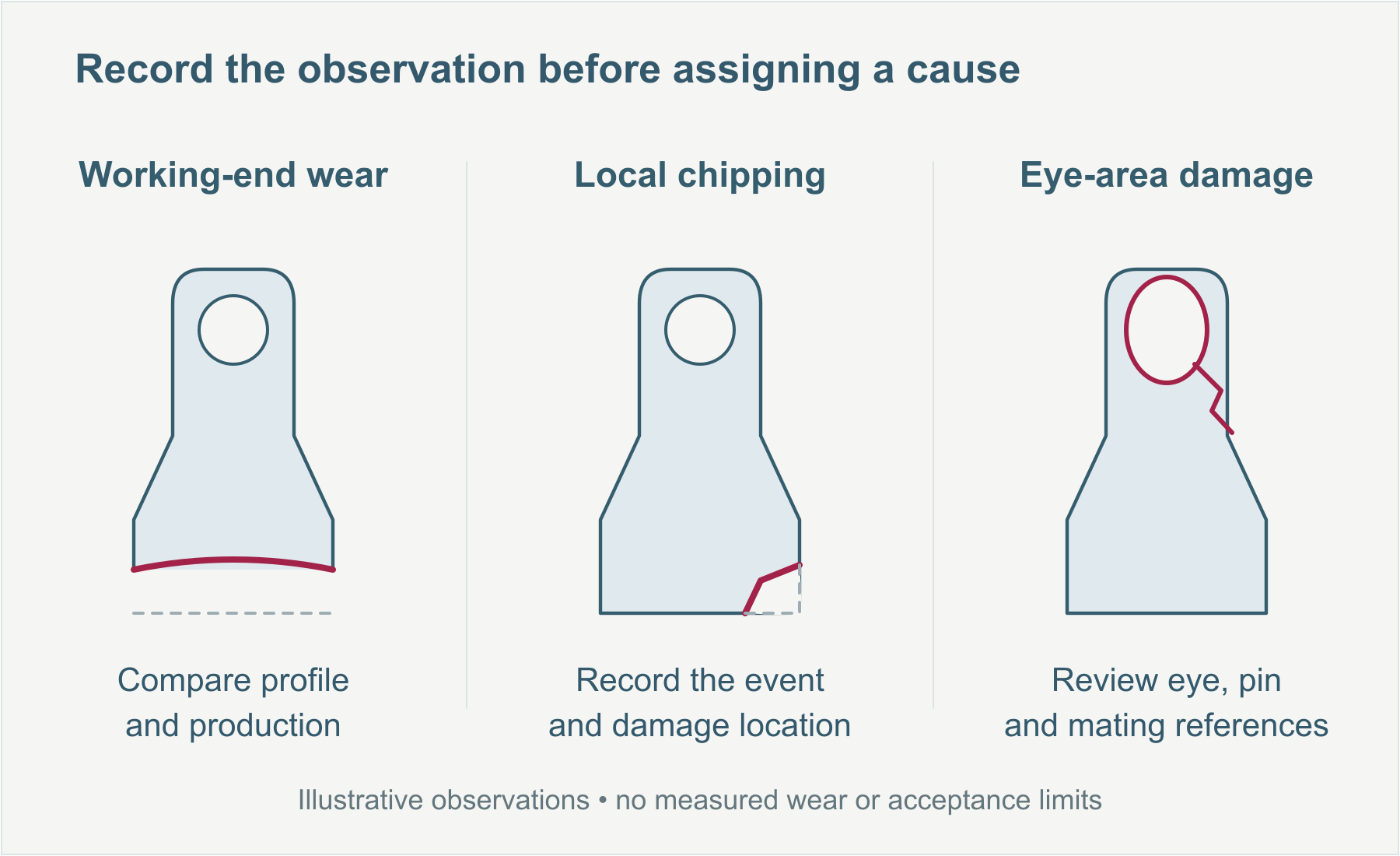
Compare the working end with the rest of the set
For gradual consumption, ask whether the hammer is losing useful crushing profile before its planned replacement. Mass loss and profile loss describe different things. Two hammers can lose similar mass while retaining different working shapes.
Use the same orientation in each photograph. Record the rotor position, the face in service and any permitted turning or position change. If a hammer moves, preserve its identity and start a new position interval; otherwise, wear from two locations may be attributed to one location.
Compare processed tonnes or operating hours over a defined period. Fewer calendar days do not necessarily mean faster wear. Also note changes in top size, source material, moisture, throughput or crusher settings. If those conditions changed, the comparison still has value, but it no longer isolates the alloy.
A hypothetical recording example is: “Hammer H07, position R2, working end viewed from the drive side. Feed source changed during this interval. The opposite face was not used.” It preserves the part, location and operating change rather than simply reporting “poor wear life.”
Calculate a wear indicator without losing the failure mode
For the same identified set, weighed before and after a defined operating period on a consistent basis, calculate:
Recorded set mass loss, g/t = mass difference in kg × 1,000 ÷ verified tonnes during that interval.
For a hypothetical difference of 24 kg after 60,000 t, the result is 24 × 1,000 ÷ 60,000 = 0.400 g/t. The denominator is the crusher throughput for the interval, counted once; it is not multiplied by the number of hammers.
Use the same cleaning and weighing basis and retain the starting mass of the same identified components. Turning a hammer does not create another new hammer. A partial replacement requires its own entry/exit record. If a section broke away, record whether recovered fragments were included in the final weighing. A difference that includes missing fragments cannot be labelled entirely as gradual abrasive consumption.
The same g/t can lead to different replacement decisions
Consider two hypothetical records measured on the same cleaning and weighing basis. Set A loses 12 kg over 30,000 t; set B loses 24 kg over 60,000 t. Both give 0.400 g/t. B's larger total loss does not establish a higher normalized loss rate.
Now separate the outcomes. If A reaches its planned change with the working profile gradually consumed, while B is removed after a local section breaks, the common g/t does not make those outcomes equivalent. B's record includes missing material from a different failure mode. Compare the remaining geometry and removal reason before choosing the next trial objective.
- Gradual profile loss controls removal: compare repeated profile measurements at defined points against verified throughput under comparable feed and product conditions.
- A local fracture or damaged eye controls removal: investigate that region, its material condition, geometry and mating parts; a set-average number cannot locate the initiating problem.
- The operating duty changed: retain the result as a campaign record, and identify the changed variables before attributing it to the alloy.
Use these hypothetical records to choose what to investigate next. They do not identify a root cause. Compare component cost per tonne separately from recorded mass loss.
Treat eye and pin damage as an interface question
Damage near the mounting eye deserves its own investigation. The remaining shape of a worn bore does not establish the nominal bore size or the intended clearance to a replacement pin. Identify the applicable drawing and examine the mating components together.
A published study of a cement-plant hammer crusher investigated wear together with deformation and cracking around hammer eyelets, using mechanical analysis to examine geometry and loading. It supports considering more than alloy selection; its findings do not diagnose another machine from a photograph.
Describe whether the observed condition is bore enlargement, local deformation, a visible crack, or damage to a retained pin. Do not group all four under “abrasion.” Where cracking or breakage is involved, the examination scope and continued-use decision belong to the responsible technical personnel and applicable machine requirements.
Connect the damaged eye to its load path
The mounting eye transfers load through a contact region into the pin and its supporting arrangement. The investigation therefore needs the interface geometry and the mating-part condition, not just the hammer's alloy designation. An altered bore shape is an outcome to document; copying it into a replacement would also copy a geometry whose original dimensions are unknown.
The cement-plant study combined particle-flow simulation, stress analysis and maintenance records. For another crusher, establish the actual geometry and loading, then test whether the proposed explanation accounts for the observed locations. Its revised design cannot be adopted from the study alone.
Swipe or scroll to see all columns.
| Investigation question | Useful evidence | What it does not establish alone |
|---|---|---|
| Does the part match the ordered material? | Traceability and composition results linked to the relevant component and specification | That the material was appropriate for the duty, or that every region has the required structure |
| Is the hardness condition consistent with the requirement? | Test method, locations, preparation and results for the specified constituent | Toughness, complete heat-treatment history, or the cause of a particular fracture |
| How did the damaged region deteriorate? | An examination plan connecting the fracture/surface, local material condition, geometry and operating history | A unique root cause from one close-up or one laboratory result |
This table is an evidence plan, not a required test package for every enquiry. The responsible examiner should select the work that can distinguish the remaining explanations.
When is a material change worth testing?
A material trial has a clearer purpose when the current part and its operating conditions are understood. If gradual working-end consumption is the main limitation, compare candidate constructions against the documented impact and abrasion conditions. If local fracture or interface damage controls removal, investigate those features before assuming that greater hardness will improve the result.
Define the problem the trial should address, retained geometry, proposed changes and observations that will determine success. Describe the construction as well as the alloy, so the inspection request matches the part being evaluated.
Match the construction and test coverage to the proposed hammer
Keep four items separate in the proposed drawing and inspection record:
- Base material: full grade, specified condition and the regions it forms; link composition and hardness results to the relevant heat or batch.
- Inserts or reinforcement: constituent, layout and revision, with evidence for that construction. “Carbide” alone does not identify a particular carbide chemistry.
- Hardfacing: covered region, layer requirements and the corresponding thickness/hardness methods and locations.
- Finished hammer: mounting geometry, working direction, individual mass and rotor position, with drawing-based dimensions and the required weight groups.
For bimetallic or ceramic-composite proposals, identify each region and its connection or reinforcement arrangement. Matrix results do not cover every constituent. Use the hammer inspection-report guide to connect these requirements to the records.
Check coverage alongside the values: a heat-level composition row, sample readings and per-piece checks cover different populations. Ask which part identities, locations and quantities each record represents. A factory self-inspection record is not independent third-party certification; neither the order quantity nor a “100%” heading establishes that every hammer received every test.
Set a comparison rule before installation
Define success in terms relevant to the plant: retaining the required profile, reaching a planned change window, reducing abnormal damage, or lowering component cost per verified tonne. Keep throughput and product requirements in the comparison.
Record the new set, material route, installed positions, production basis, interventions and actual removal reason. If several features change together, report the combined result rather than assigning the whole difference to the material.
Assess each option in three steps: confirm fit and the applicable acceptance requirements; check the work performed while the required throughput and product were maintained; then evaluate the removal reason, remaining profile and cost. A lower recorded cost does not compensate for unmet fit, throughput or product requirements.
Where practical, repeat a comparison under comparable duty and retain the campaign-to-campaign spread. One set ending after a feed change and another ending after a fracture cannot isolate a material effect, even if both records contain precise tonnages. State which variables remained comparable and which changed.
Keep the mass-loss indicator and component cost per tonne as separate outcomes. A lower purchase cost can reduce cost per tonne even when recorded mass loss per tonne is higher. Preserve the campaign scope, part count, construction and operating changes with either result. For the calculation, use the cost-per-tonne method.
Discuss the next hammer requirement
Start with the hammer reference or photographs of the whole part, working end and mounting end, together with a short description of the damage. Add the machine reference and a way to contact you. If the quantity, grade or verified tonnage is not yet known, identify that gap so the discussion can begin with the information available.
For the proposal, add a position list with each hammer reference, drawing revision, direction, installed quantity, spares and weight basis. Show the mounting end and retained pin/spacer condition; list extra components you also need to buy.
ZL provides drawing support free of charge, including new designs and multiple revisions. For a first overseas order, single-piece or small-batch requests can be considered, with feasibility and supply scope established during quotation. Dimensional, weight and material verification can be defined against the part drawing, with methods and acceptance criteria recorded for that order.
Review the hammer product or send the part and wear record for review.
Frequently asked questions
Does a broken hammer mean the alloy was wrong?
It is one possibility to investigate. Damage location, feed events, support and mating interfaces, geometry and material records must be considered together.
Can a worn hammer be copied directly?
It can help identify the part, but wear has changed its shape. Replacement geometry needs an appropriate drawing, preserved references or a verified engineering basis.
Are service days enough to compare two materials?
They are a starting record. Operating hours, processed tonnes, feed changes and the reason for removal make the comparison more useful.
Does a set weight record verify rotor balance?
Individual hammer weights, position groups and rotor balance verification describe different checks. State the required assembly configuration, method and acceptance basis for each applicable check; a matching total set mass does not replace those records.